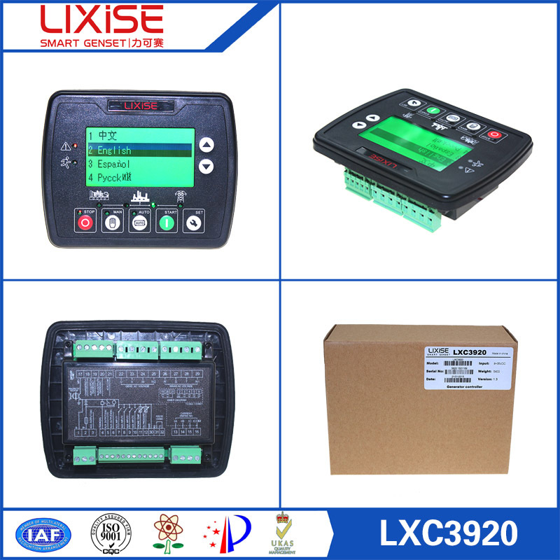
| Packaging Details: | Dimensions 143mm x 115mm x41mm Material: PE bag & Hard paper box. |
|---|---|
| Delivery Detail: | in stock |
LXC3920 diesel generator set control panel manufacturer

LXC3920:Based on LXC3120,add RS232 interface and can be remotely monitored by LXI680
integrated with related PC software.s Its n main s features e are s as follows:Display :132×64 LCD with emerald green backlight;
Language :Chinese, English, Spanish and Russian;Operating :good feeling button pushing, long button life;Suitable for :3-phase 4-wire, 3-phase 3-wire, single phase 2-wire, and 2-phase 3-wire systems withvoltage 120/240V and frequency 50/60Hz.
Protection: Automatic start/stop of the genset, ATS(Auto Transfer Switch) control with perfect faultindication and protection function;Output Control :With ETS, idle control, pre-heat control, speed raise control and speed drop control,All output ports are relay-out;
Parameter Settings :All the parameters can be adjusted using front panel of the controller or use thecomputer through USB to connect directly to controller settings, all is not lost when power downparameter system;Sensor Detection :More kinds of curves of temperature, oil pressure, fuel level can be used directlyand users can define the sensor curves by themselves;Multiple rank Dtisconnect Conditions : s Gens l frequency,speed,oil pressure,D+;Widely r Power supply range: DC(8~35)V, suitable to different start battery voltage environment;
gounting Assembly :Modular design, anti-flaming ABS plastic enclosure, plug gable connectionterminals and embedded installation way; compact structure with easy mounting.
LXC3920:When mains is abnormal (over/under voltage, loss of phase), enter into “Mains AbnormalDelay” and LCD displays count down time. When the delay is over, “Start Delay” timer is initiated.“Start Delay” countdown will be displayed on LCD. When start delay is over, preheat relay energizes (if configured), “preheat delay XXs” information willbe displayed on LCD.After the above delay, the Fuel Relay is energized, and then one second later, the Start Relay isengaged. The engine is cranked for a pre-set time. If the engine fails to fire during this crankingattempt then the fuel relay and start relay are disengaged for the pre-set rest period; “crank rest time”begins and wait for the next crank attempt.Should this start sequence continue beyond the set number of attempts, the start sequence will beterminated, the first line of LCD display will be highlighted with black and Fail to Start fault will bedisplayed.In case of successful crank attempt, the “Safety On” timer is activated, allowing Low Oil Pressure,High Temperature, Under speed, Charge Alternator Failure and Aux. inputs (configured) to stabilizewithout triggering the fault. As soon as this delay is over, “start idle” delay is initiated (if configured).During “start idle” delay, under speed, under frequency, under voltage alarms are inhibited. When thisdelay is over, “warming up” delay is initiated (if configured).After the “warming up” delay, if generator status is normal, its indicator will be illuminated. If generatorvoltage and frequency have reached on-load requirements, then the generator close relay will beenergized; genset will take load; generator power indicator will illuminate and generator will enter intoNormal Running status. if voltage or frequency is abnorm
LXC3920:During normal running process, if mains normal, enters into “Mains Normal Delay”. Whenmains indicator illuminates, “Stop Delay” begins.LXC3X10:When the “Remote Start” signal is removed, the stop delay is initiated.Once this “stop delay” has expired, the Generator Breaker will open and the “Cooling Delay” is theninitiated. After “Transfer Delay”, the mains close relay will be energized; mains will take load;generator power indicator will extinguish while mains power indicator will illuminate.During “Stop Idle” Delay (if configured), idle relay is energized.“ETS Solenoid Hold” begins, ETS relay is energized while fuel relay is de-energized. "Fail to Stop Delay" begins, complete stop is detected automatically.Generator is placed into its standby mode after its complete stop. Otherwise, fail to stop alarm isinitiated and the corresponding alarm information is displayed on LCD.
The main technical parameters
| Operating Voltage | DC8.0V continuous power supply to 35.0V |
| Power consumption | <3W (standby mode: ≤ 2W) |
| Alternator voltage input: | 15V AC - 360 V AC (ph-N) |
| Phase four-wire | 15V AC - 360 V AC (ph-N) |
| Two-phase three-wire | 15V AC - 360 V AC (ph-N) |
| Single-phase two-wire | 30V AC - 620 V AC (ph-ph) |
| Three-phase three-wire | |
| Alternator frequency | 50 Hz / 60Hz |
| Speed sensor voltage | 1.0 to 24V (rms) |
| Speed sensor frequency | Maximum 10000Hz |
| Start relay output | 5A DC28V DC power supply output |
| Programmable relay output 1 | 5A DC28V DC power supply output |
| Programmable relay output 2 | 5A DC28V DC power supply output |
| Programmable relay output 3 | 5A DC28V DC power supply output |
| Programmable relay output 4 | 5A AC250V passive output |
| Programmable relay output 5 | 5A AC250V passive output |
| Dimensions | 143mm x 115mm x41mm |
| Hole size | 110mm x 90mm |
| Current transformer secondary current | Rated: 5A |
| Working conditions | Temperature: (-25 ~ 70) ° C Humidity: (20 ~ 93)% RH |
| Storage conditions | Temperature: (-30 ~ +80) ° C |
| Protection class | IP55: When installed between the controller and the control panel when the waterproof rubber ring. |
| IP42: When between the controller and the control panel when not fitted waterproof rubber ring. | |
| Dielectric Strength | Object: Input / Output / Power |
| Reference Standard: IEC688-1992 | |
| Test Method: AC1.5Kv/1min leakage current 3mA |
